Shay Components 1 ... 2 |
Geared Steam Locomotive Works ©
Steam Cylinders
- Vertical Positioned
- Unlike the symmetry of the cylinder location on the Climax and Heisler locomotives, the Shay's were most often positioned vertically and located on one side, the right side. The entire boiler was offset to the left of the frame to accommodate and compensate, weight wise, for the the cylinders and their housing. The smaller Shay's (below 20 tons) used only two cylinders. The larger units utilized three cylinders.
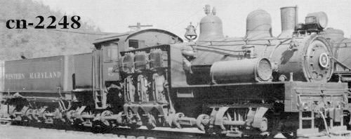
Tilted Cylinders
Inward
Inward
Outward
- Tilted Position
The cylinders on a very few Shays were noticeably tilted a few degrees inward (from vertical) toward the boiler. A known exception to the inward tilting was on Western Maryland's #5, where at one point in its life, the tilt was actually pointed outward, away from the boiler. One known reason for the tilting was as a result of the need to change the locomotive's operating gauge. Since it was virtually required that the line shaft remain as straight as possible all along it's entire length, the crank shaft below the cylinders had to be moved inward or outward accordingly and thus the tilt in the cylinders.
It is not known if the tilting was a factory installation feature or it was always applied after it was originally constructed.
Drive Mechanism
Within the openings of the shroud called the "bottom bracket" at the base of each cylinder unit in the photo above , you can see where the piston rods connect to the crank shaft. Each of the three connections being offset a specific number of degrees to provide smooth steady power. The crank shaft is similar to those utilized in automobile engines, except these are larger and exposed to the elements. Just beyond each end of the "bottom bracket" can be seen the first universal joints. These are the thick round black disks with bolt protruding. These joints can flex as needed to provide steady power to the drive shaft parts along the right side of the engine and allow for power transmission to the trucks even when they are negotiating a curve. In the photo above, note the downward angle of each drive shaft as it comes out of the universal joint going downward to connect to a universal join on the first set of trucks on either side of the "bottom bracket".
Crank Shafts
The company produced three models of crank shafts. One model was for the two cylinder engines. A midsized model was made for the three cylinder, two truck shays. The third and largest (pictured above) was for the three cylinder, three & four truck engines. Noted by numbers 1, 2, & 3 in the picture are where the corresponding cylinder's connecting rod was attached. Note that each is progressively offset from the other. 4 points to the part of the shaft that connects to a square shaft with the help of a coupling ring. This connection is called the universal joint. This "Y" in the crank shaft mates or inserts perpendicularly to the corresponding "Y" the "line shaft". This joint is similar to that used on a rear axle automobile. The opposite end of the square shaft would then be similarly connected with a coupling ring to a line shaft.
Square Shafts
These were basically the extension units or "middle men" along the entire drive
shaft mechanism. The "Y" end of each shaft would connect to a
corresponding "Y" on a crank shaft or line shaft with a coupling ring.
Each square shaft unit actually consisted of two pieces. One was
a square hollow sleeve into which the other component, a square solid shaft,
was inserted. The various sizes and styles manufactured by Lima can be
seen by clicking on the image above. The image of each is a "cut away"
depicting only one end of the shaft.
Line Shafts
The line shafts were attached to the right side of each truck. Each had two beveled gears that meshed with corresponding beveled gears attached to the outside of the left wheel of each truck. The "Y" end of the shaft noted by the 4 in the image above, connected to a square shaft a coupling ring. The particular shaft pictured just above was used on the front truck of the Shay. The ones in the mid section of a 3 or 4 truck shay had a "Y" end connector at both ends.
Trucks
As with the Climax, Heisler, and most other geared locomotives, the Shay had sets of two to four "trucks". Similar to the other geared locomotives, all wheels on the locomotive were powered. Each truck on the Shay consisted of two wheel sets (2 wheels and an axle) with beveled drive gears attached to the outside of those wheels located on the left side (facing the locomotive from the front) of each wheel set. This differed from the Climax and Heisler whose truck drive gears were centrally attached to one or more axles of each truck.
In the image just above, you will notice the beveled gears on the left wheels and the front line shaft with its beveled gears that meshed with those on the wheels each was attached to. The connecting ends of the shaft, noted by the 4, were attached, to a part called the square shaft with a coupling ring.
The particular trucks in the image above are of the arch bar type. This type of truck were manufactured in the early part of Lima's production of these locomotives. This type of truck was also used on rolling stock, such as box cars, flat cars, and cabooses during this early period of railroading. Basically speaking the "arch bar" truck frame consisted of strips of narrow steel bar stock bent into the necessary shapes and attached to similar adjoining bar stock with nuts and bolts. In later years of manufacture, the truck frames were made of of cast steel like in the image just below
Page changed: March 25, 2019 08:03:07 PM